|
Conversion of Lathe to CNC
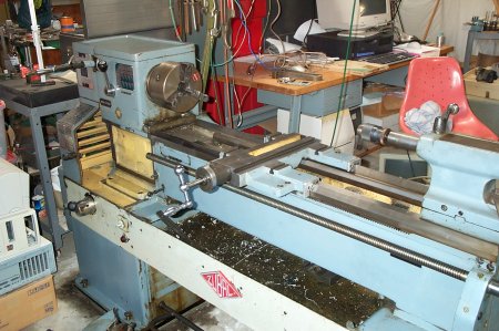
This page will contain pictures and notes on the conversion of a 14" x 36" engine lathe. This is my first project of this type so the initial goal will be to just get the X and Z axii working in the most basic form. I planned on leaving the spindle alone, but while on eBay I saw a VFD that had my name on it. I am a Linux fan, so I intend to use NIST's EMC for the motion control software. New pictures are added to the bottom of the page. |
|
|
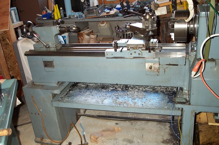
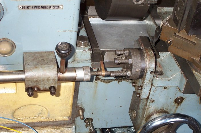
The picture to the right shows the easy part of the project, which was removing the uneeded bits. Actually the the lead and cross screws shown here will be replaced with ballscrews. A bracket and X axis motor will bolt to the bottom front of the carriage, where the gearbox used to be. A bracket and Z axis motor will mount to the yellow area to the left where the headstock gearbox used to be. |
|
|
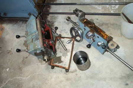
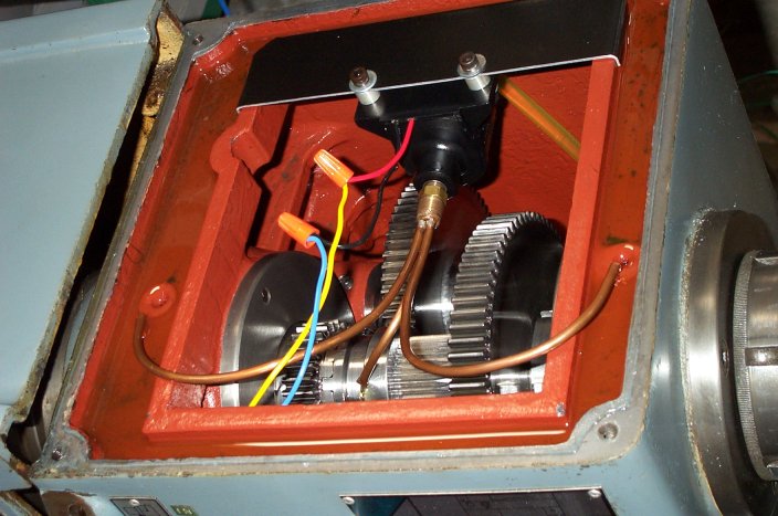
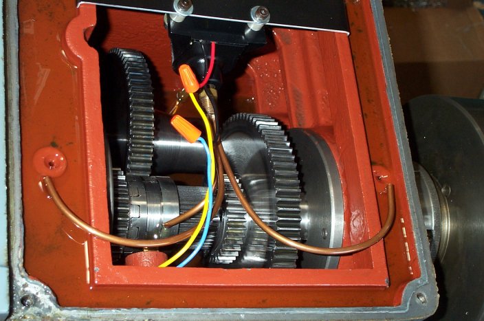
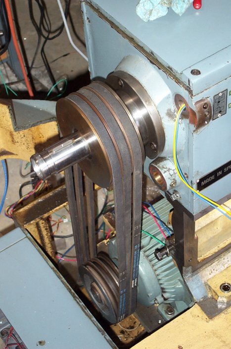
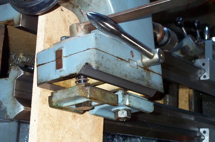
The feed/threading gear box is on the left. To the right is the carriage gearbox. |
|
|
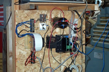
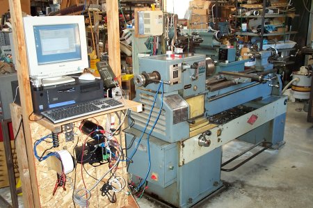
I made this stand just to get a first pass on getting a working system. Once I get an idea of what parts are needed and where they need to be, I'll start thinking about making an enclosure to make it look purdy. The main parts shown here are the 100VDC motor power supply and the AC servo motor controller. On the left of the picture is a toriod 110VAC to 72VAC 800Watt transformer from Antek (Link -> http://stores.ebay.com/Antek-inc). Just above and right is the diode bridge on two square plates. To the right of the bridge is a 160v 33000uf capacitor. To the right of the capacitor is a ribbon cable to the PC. Below the capacitor is the Rutex chassis and R2030 AC driver cards. Between the chassis and the trans former is the 24VDC power supply for the Rutex chassis. |
I still need to add an e-stop and braking resistor system. |
|
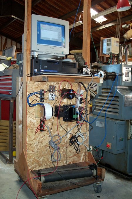
Here is an overall view of the test stand. On the PC screen is the Rutex tuning software. At the bottom of the stand is a variable resistor that I had to use as a bleeder resistor for the capacitor. I plan on replacing it with a 10kOhm 2Watt resistor mounted to the capacitor terminals. The X axis motor is barley visible under the voltmeter to the lower right of the computer screen. It is a Sanyo Denki P50 1000 Watt brushless AC servo motor (model: P50B08100VCKS7). The Z axis will be driven by another P50. |
|
|
|
|
|
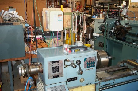
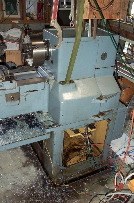
The beige object in the upper middle of this picture is the VFD. |
|
|
|
|
|
|
|
|
|
|
|
|
|
|
|
|
|
|
|
|
|
|
|
|
|
|
Random Notes: Encoder Resolution: 8000 pulses/rev., 2000 quadrature cycles/rev.
|
|