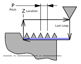
- J~ - Initial, or first pass depth of cut (diameter or radius depending on mode, G7 or G8). This value is always positive, but I determines the direction that it is applied. The depth of cut for subsequent passes is adjusted by the R parameter.
- K~ - A positive value (diameter or radius depending on mode, G7 or G8) specifying the full thread depth. The final threading cut is K beyond the thread peak position.
Optional Parameters
If these parameters are missing in the command line, they are set to the default values listed below. If the parameter letter is used but a value is not included, this produces an error.
- R~ - Depth of cut degression, defaults to 1.0. This option allows for an automatic decrease in depth of cut. If the depth of cut remains the same for each pass, the amount of a 60 degree tool's cutting face and load increases rapidly. Decreasing the depth of cut for each pass helps to equalize the load. A value of R2.0 provides a depth of cut that equalizes the chip area, but also increases the number of passes needed to complete the cycle. (Figure 5)
- Q~ - Compound slide angle, defaults to 0 degrees, typical values are 29.0, 29.5 or 30.0 for 60 degree thread forms. (Figure 4)
- H~ - Spring passes, defaults to 0. This repeats the last pass H number of times.
- E~ - Specifies the distance in the Z direction used for the entry/exit taper. For a 45 degree entry/exit taper program E equal to K in radius mode, or E equal to K/2 in diameter mode. (Figure 6)
- L~ - Specifies which ends of the thread get the taper. Program L0 for no taper (the default), L1 for entry taper, L2 for exit taper, or L3 for both. (Figure 6)
- D~ - Offsets the far end of the thread cutting pass (diameter or radius depending on mode, G7 or G8) to provide a taper for tapered threads such as with pipe threads. (Figure 7)
An error message will be presented and execution of G76 prevented if:
- All the required words; P~, Z~, I~, J~, and K~ are not specified.
- Other axis words, such as X~ or Y~, are specified.
- Any of P~, J~, K~, H~, E~, or L~ have negative values.
- E~ is greater than half the distance between the starting Z position and Z~.
The tool will pause at the start of the synchronized path until the spindle's index triggers motion. A heavy cut may result as the tool rapids to and waits at the start if there is material at this location. To prevent this the path is usually set to start away from the workpiece. If an entry end taper is specified, the synchronized path starts earlier at a location intended to be the OD of the stock on the last pass, so usually has clearance.
Once synchronization is triggered, it takes a short distance for the motion to stabilize, so the start should also be away enough to allow motion to stabilize before cutting starts on the workpiece.
The end of the synchronized path can also have problems in that a rapid retract is started immediately at the end. This produces a cut that ramps away dependent on the rapid rate rather than spindle position. If the spindle speed changes between passes the ramp shape will change and can produce a heavy cut. Keeping the spindle speed constant for all passes, or using an exit taper, or removing material at the end of the thread can prevent this problem.
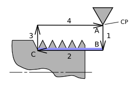
Leg 4 (Figure 1) is intended to be a tool clearance path. Motion on this path should be set to be safe from hitting the workpiece on the front of the tool and also safe from obstacles on the back side of the tool and tool holder. Travel beyond the tool clearance may be a problem in tight places such as with internal threads. An issue is that the synchronized path shape is set by the final pass and is used from the first to last passes. If end tapers are used with a short tool clearance, I less than K (Figure 8), the tapers can go beyond the clearance, so use caution.
|
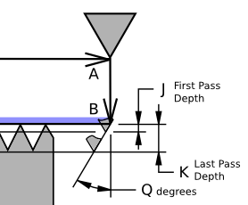
Figure 4
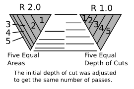
Figure 5
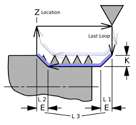
Figure 6
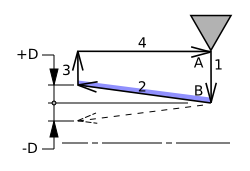
Figure 7
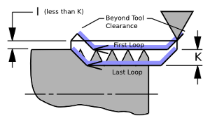
Figure 8
|
|
Starting with the last pass and working out, and using the 1/4-20 specifications:
- Pitch P = 1/TPU = 1/20 = 0.0500
- Pitch Diameter = 0.2164 to 0.2127, center 0.2146, +/- 0.0019
- Major Diameter = 0.2489 to 0.2408, center 0.2449, +/- 0.0041
- Root Width = P/8 = 0.0063
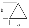
Calculate the X distance from the tool tip to the tool pitch line. This equals the distance from the pitch line to the 60 degree vertex minus the distance from the flat tip to the vertex. Using the equilateral triangle formula:

h = 0.8660 * a |
 |
For this example, let's say the 60 degree tool has a .0063 wide flat (Root Width) on the tip.
h = 0.0063 * 0.8660 = 0.0055
For the pitch line width of P/2:
h = 0.0250 * 0.8660 = 0.0217
0.0217 - 0.0055 = 0.0162
The pitch diameter for a 1/4-20 thread is 0.2146.
Subtract 2 * 0.0162 to get 0.1822, which is the diameter of the tool control point on the last pass.
K = Major diameter - last pass diameter = 0.0627
Which we plug into the G76 command above.
I, tool clearance, and J, first depth of cut, are fairly arbitrary and don't require math to set. Add I to the major diameter to get the the start X for the G0 move in the G-code above
Another way to do this using a micrometer and a test workpiece is to cut a feature on the test piece that indicates where the pitch line is on the tool.
The process is to cut a smooth diameter on the test piece. Measure it with a micrometer and jot down the value. Next, touch-off the threading tool tip to the test piece (See area A in Figure 10) and enter the touch-off value (plus the gauge width if used). The X DRO will now indicate the control point diameter which is our temporary pitch diameter. Position the tool close to the end of the workpiece, zero the Z position, make a cut about P/4 into the workpiece (See area B in Figure 10), jot down the X value, retract, jog accurately over P/2 in Z, make another cut at the same depth as the first cut. Inspect the flat between the grooves (labeled C in Figure 10) with a loupe. Repeat the pair of cuts, making sure to make them at equal depths until the flat just comes to a point. Record the depth and subtract from the touch-off value. The result is the diameter depth between the tool tip and the pitch line. (Divide by 2 to get the radial depth if needed.)
|
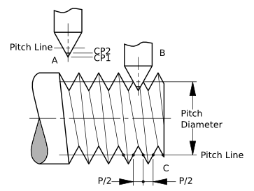
Figure 9
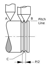
Figure 10
|