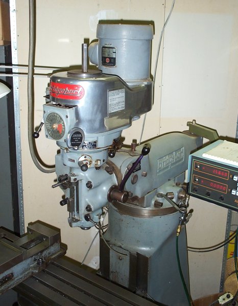
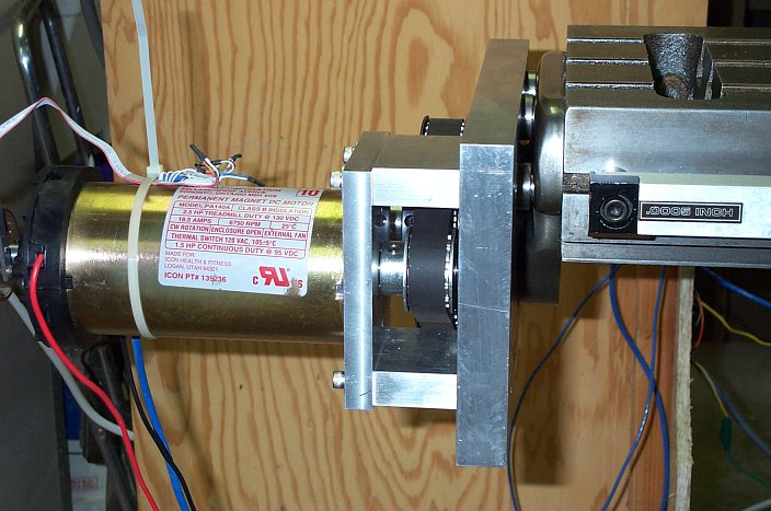
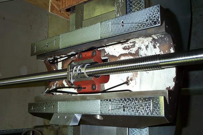
The motor is a treadmill motor from surpluscenter.com. The pulleys are from B and B Machine, 40x3/4, QD bushing and 13x3/4 . I designed this assembly to need the least amount of work to get something decent working. From there, I could evaluate how it worked and design a new system utilizing the knowledge gained. I also find that when I do a jury design, I tend to not go onto the refined design stage, so I tried to make up a system I could live with for a while. During design, some of the issues that came to mind were, that there is not much to mount the assembly to - just four closely spaced bolts. To make things worse, the main plate needs to be spaced away from the table to allow full table travel. I am losing about 1.5" of travel with the current arrangement. By keeping the handwheel bearing mount, there was no stable surface to mount the main plate to, other than the four counter-bores in the mount. It turned out that each counter-bore had its own diameter and depth and took some tweaking to get the end of the spacers to be on a single plane perpendicular to the table. I would have thought Bridgeport could make four of the same type of holes the same size. I didn't want to use key-ways or set-screws to transmit torque between the pulleys and shafts, so I tried to to use QD bushings which (I believe) are designed to use bore clamping as the primary fixing agent. Because the motor is rated at around 6000 RPM, I guessed that a 4:1 ballscrew to motor ratio would be best. I had to compromise at 40:13 and use set-screws on the motor pulley. I'll be watching the motor pulley to see if the set-screws become a problem. Originally the lead-screw, bearing and hand-wheel are fixed to each other through compression and key between a nut on the end of the lead-screw and a boss on the lead-screw. In order to use the ball-screw without modifications, I needed to keep the same arrangement (minus the key). A problem comes about in that, if I tighten the QD bushing, the screw nut can't transmit compression to the bearing mount. If I tighten the screw nut first, the QD bushing bore may be kept from tightening to the shaft. Right now, I am tightening the nut just enough to take up slack, then I tighten the QD bushing and then a final tightening of the ball-screw nut. This will be another thing to keep an eye on.
|
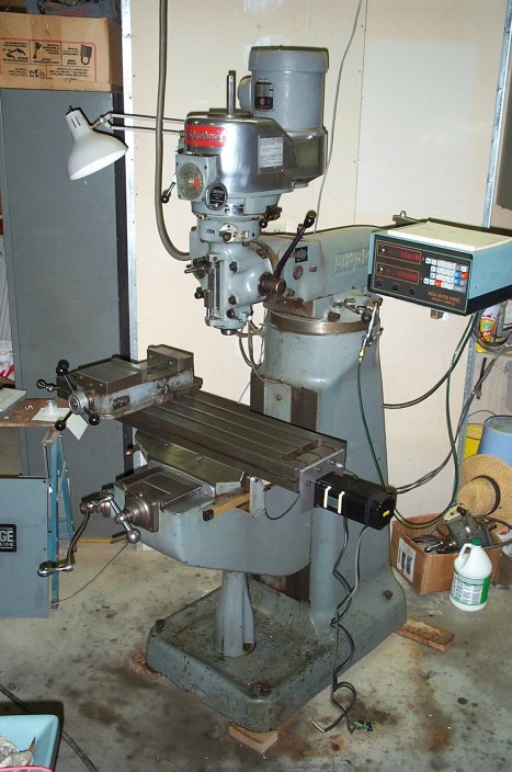
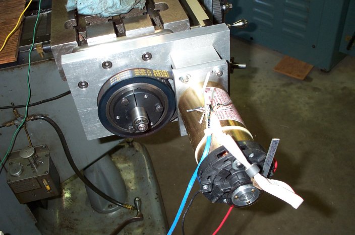
What encoder to use and where to put it was an issue I put off for this stage. I have been partial to using a linear slide for position feedback because this seemed to be the shortest path between the table position and the measuring device. It turns out that if you have any backlash (I have .002 inch), the controller may see several control cycles of no movement. For each cycle, more motor power is applied so that by the time the controller gets an indication of movement, the motor is moving too fast, so the controller tries to cut the output to the motor. This makes for an unstable system which was confirmed during my testing. In the picture above you can see my jury rigged motor encoder which I was able to tune to perform quit well, except for position errors due to backlash. The slide system was unstable but always seemed to come to a final position within the accuracy of the slide (.0005 inch). The plan now is to mount an encoder to the end of the ball-screw. Coming up with a mount with out any flex and going around the large screw pulley is going to be a challenge.
|
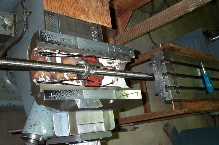
Here is the source of much grief. The following is not meant to be wining, but a warning. I have done allot of cruising of the Internet for information on ball-screws and for the do-it-yourselfer, I found very little information or sympathy. I had seen the most amount of "chatter" about Hiwin. I checked out there website and ordered their retrofit kit hoping that somehow it would be appropriate for my application. I have no qualms about the quality of the product, but if you order ball-screws from Hiwin, you need to beware of two things. Unless a specification is plainly stated, don't make any assumptions. The retrofit kits screws are not zero backlash screws and are not adjustable. In fact the backlash is springy so in my opinion, which I haven't throughly tested, is that not only are these screws unusable for CNC, their performance for a manual machine is in question. Another thing to watch is that the ordering information indicates that the kit you need is based on table size. This is half true. The X parameter is the table length in the X direction. The Y parameter is the Y _travel_. I ordered a kit for my 42 x 9 table and came up 3 inches short for my 12 inch Y travel. The response I got from Hiwin was that I could still use the yoke if I wanted to buy another set of custom screws from their zero backlash line.
I still have yet to see anything of ballscrews I paid for from marchantdice.com more than a year ago. The ball-screw market seems to be a rough place and you need to be careful.
|
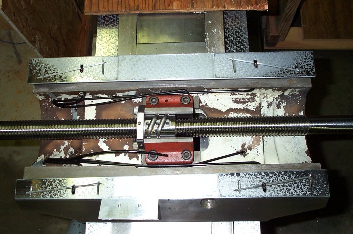
The good things about the screws is that, they are beautiful and a big improvement as far as reduced torque and smoothness. Even though the backlash is springy, I am finding for manual machining that running the gibs tighter than I used to, preloads the spring out. Even with moderate gib tension the torque required to move the table is lighter and smoother than the old lead-screws.
|