Notes on using Synergy with EMC2
I have been creating g-code by hand to use with my CNC machines. This doesn't allow me to use CNC for its real advantage, which is to make parts with complex compound shapes and large numbers of features. A method of automating the creation of g-code is the only practical method of coping with this complexity.
Synergy is not open source, but it is Linux based and affordable and seems capable of doing everything I need. So far learning to use it has been a problem. This page will contain my notes on getting Synergy to become part of the work flow in my shop.
Synergy is a product of Weber Systems, Inc., http://webersys.com/
I will try to document,in detail, the creation of a simple part. Please feel free to let me know how I can improve this page at kwallace+at+wallacecompany.com.
I am using Synergy with Fedora Core 4. I would like to look into using it with the latest Ubuntu LTS version. There are a number of Synergy versions that match different older Linux distributions, so I don't know how successful using Ubuntu will be.
I start Synergy with:
/usr/weber/bin/synergy
in a root terminal ("su -"). I should be able to start Synergy as a normal user but the software key doesn't work due a permissions detail I haven't addressed yet.
Bob Schuppel from Weber Systems wrote:
|
(
NOTE:
Once permissions are set properly you can create a desktop launcher for double-click access.
The /usr/weber directory tree defaults to being owned by root.
The concept here is that single end users would change the ownership of the entire tree to an active user with:
chown -R USERNAME /usr/weber In the case where multiple users need access, administrator ( root ) would create a group to which users needing access could be added. Create group with:groupadd NEWGROUPNAME
[
modifies the /etc/group file.
You can manually add users to the group by listing them after the group name using your favorite editor or a graphical tool available in most distros
]
Reassign permissions with:
chown -R ANYUSERNAME:NEWGROUPNAME /usr/weber
Users can login to a new group with:
newgrp NEWGROUPNAME
)
(Thank you Bob. - I still get a Solids not available message.(2008/05/20))
|
Controlling the permissions of these two files will control the access to the licensed features.
|
/usr/weber/bin/.tcp_stat
/usr/weber/etc/.hist_back
You could use:
chmod 666 /usr/weber/bin/.tcp_stat /usr/weber/etc/.hist_back
|
In summary: to control access to basic Synergy, set permissions for /usr/weber (recursively); for licensed features set permissions on /usr/weber/bin/.tcp_stat and /usr/weber/etc/.hist_back
There are help messages, tutorials and animations available, but I have found these to be difficult to use. I prefer to have help a system that I can consult independently from the normal Synergy program, so that I can read the help material in one window and do the procedures in a normal Synergy window. A dual screen PC might be nice for this.
Bob to the rescue again:
|
(
NOTE:
You can have as many copies of Synergy running as system resources allow. You might start another copy of Synergy on a second desktop that is used only for documentation. Click the button above the help area far right with the scroll to prevent auto-update of the help page when mouse hovers over a button. Then use GNOME desktop switching to jump back and forth.
)
|
One thing that helped with the animations is printing the animation script files (.ply) in /usr/weber/http/playbacks. I printed a script to paper (yuck) and went through the animation while single stepping (using the Enter key) and writing command box entries and notes. This helped me to correspond which details where relevant with what command. Also, the status window for the animation hides behind my desktop menu bars, so the script print-out lets me see what I was missing.
CAM of Rectangular Path
Start Synergy
Select Construct (if not currently active)
Select dark gray from the color selector bar
Select Points
Select Input XY
The upper left should display "INPUT ABS X? REP=0"
If the text cursor is not flashing in the data entry box, mouse click on the box
Enter "0"
The upper left should display "INPUT ABS Y? REP=0"
Enter "0"
The upper left should display "INPUT ABS X? REP=0"
If the text cursor is not flashing in the data entry box, mouse click on the box
Enter "5"
The upper left should display "INPUT ABS Y? REP=0"
Enter "3"
Select "Refresh" (just below the color selector), then "Fit"
Select "Macros" from the "Construct Tab"
Select "Rectangle Two Points"
The upper left should display "CORNER RADIUS, Chamfer? REP=0"
Enter ".5"
The upper left should display "STARTING CORNER ABS X? REP=0"
We want to snap select one of the points, so go to the Input Method drop box which should have "Rectangular" in it.
Click on the box to open it, Select "Nearest"
The upper left should display "STARTING CORNER: PICK NEAREST ELEMENT?"
Place the cursor close to one of the points and click
A red rectangle should appear
Because the upper left does not display "STARTING CORNER: PICK NEAREST ELEMENT?"
Go back to the Input Methods drop down and select "Nearest" again
Place the cursor close the other point and click
You should now have a 5 x 3 rectangle with .5 radius corners
At the top left, select "Misc" and "Leave Script"
Select a color from the Color Selector
From the top left, select "Property", "Color", "Entity"
Click on each section of the rectangle to change its color
Select from the top left, "File", "Save" and click on the word "Entire" (immediately below the top left menu)
Enter a file name and select "Save"
The upper left will display "File Description?", Caution: You need to enter something or your file will not be saved
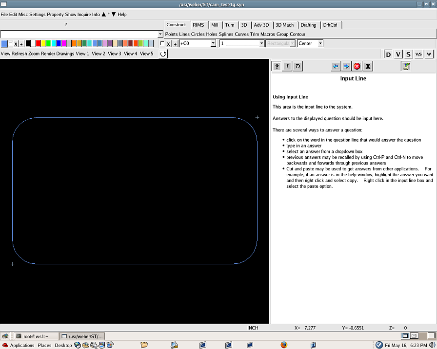
Your screen should look like this:
Now we will CAM this path
The resulting g-code could be part of a program to create a mill tool path to cut the perimeter of a cover plate.
If your rectangle file is not open...
Select "File", "Open", "Stored File"
Type an "e" in the data entry box or click on the word "Entire"
Select your rectangle file and "Open"
Your screen should look like the screen shot above
We now have an image of the cutting path, but we actually have individual sections that need to be connected to form a continuous path.
Select the "Mill" tab, then "Path" and "Auto Link"
The upper left should display "VARIATIONAL OBJECT NAME? REP=O1"
Enter an "=" in the data entry box
The upper left should display "CONTOUR NAME, Autoname? REP=A"
Enter an "a" in the data entry box
The upper left should display "PICK START ELEMENT, Single?"
Click on the left vertical edge of the rectangle
The upper left should display "NON-VDM ENTITY, RUN NON-VDM AUTO-LINK? REP=S"
Enter a "y" in the data entry box
The upper left should display "PICK START ELEMENT, Single? REP=S"
Click on the same left vertical edge of the rectangle
The upper left should display "PICK END ELEMENT, Single? REP=S"
Click on the same left vertical edge of the rectangle
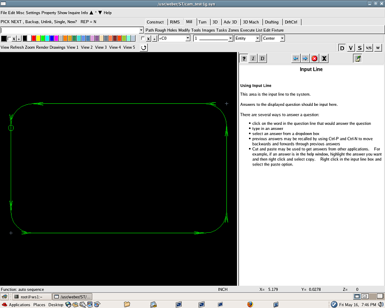
Your screen should look like this:
The upper left should display "PICK Next, Backup, Unlink, Single, New? REP=N"
We are done creating the path, so...
At the top left, select "Misc" and "Leave Script"
Select the "Mill" tab, then "Path" and "Finish Mill w leadin"
... more to come