The goal is to develop a more accurate backplot presentation in LinuxCNC. |
|
Standard [DISPLAY] GOEMETRY = XYZA |
GOEMETRY = AXYZ |
|
GOEMETRY = XYAZ |
10deg.ngc
G64 P 0.130 Q 0.025 (Path Blending)

G17 (set current plane to XY)
G90 (set Absolute Distance Mode)
G21 (set units to mm)
G54 (set current work offset)

G30 (move to preset G30)
T 1 M6 G43 H 1
S 2000 (RPM)
M3 (set spindle to ON)
M8 (set coolant to ON)

F 100

g0 x0 y0 z20
g1 x10
g0 a10
g1 x0
g0 a20
g1 x10
g0 a30
g1 x0


M9 (stop coolant)
M5 (stop spindle)

G30 Z [#1+#7] (move in Z only to preset G30)
G30 (move to preset G30)
M30 (end program)
|
|
More ideal, maybe based on G5x as rotation center. The path associated with the A axis would rotate with A. The tool would stay vertical and move in X Y Z. |
|
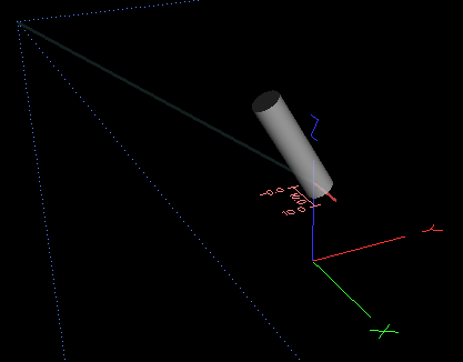
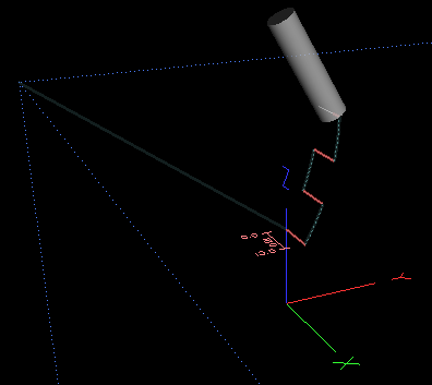
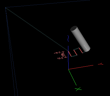
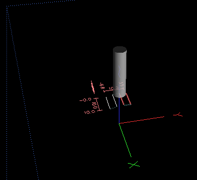
Current A axis Plot(added 2015/02/14 KW) If the A axis is enabled in the .ini file, [DISPLAY], GEOMETRY = XYZA, the A axis location or angle is represented by rotating or tilting the tool around the X, or parallel to the YZ plane. For the configuration I am considering, the tool does not physically tilt, but the tilt is an indicator that the A axis is doing something. The tilting is handled in glcanon.py/GlCanonDraw/redraw if self.get_show_tool(): pos = self.lp.last(self.get_show_live_plot()) if pos is None: pos = [0] * 6 rx, ry, rz = pos[3:6] pos = self.to_internal_units(pos[:3]) if self.is_foam(): glEnable(GL_COLOR_MATERIAL) glColorMaterial(GL_FRONT_AND_BACK, GL_AMBIENT_AND_DIFFUSE) glPushMatrix() glTranslatef(pos[0], pos[1], self.get_foam_z()) glRotatef(180, 1, 0, 0) cone = self.dlist("cone", gen=self.make_cone) glColor3f(*self.colors['cone_xy']) glCallList(cone) glPopMatrix() u = self.to_internal_linear_unit(rx) v = self.to_internal_linear_unit(ry) glPushMatrix() glTranslatef(u, v, self.get_foam_w()) glColor3f(*self.colors['cone_uv']) glCallList(cone) glPopMatrix() else: glPushMatrix() glTranslatef(*pos) sign = 1 for ch in self.get_geometry(): if ch == '-': sign = -1 elif ch == 'A': glRotatef(rx*sign, 1, 0, 0) sign = 1 elif ch == 'B': glRotatef(ry*sign, 0, 1, 0) sign = 1 elif ch == 'C': glRotatef(rz*sign, 0, 0, 1) sign = 1 glEnable(GL_BLEND) glEnable(GL_CULL_FACE) glBlendFunc(GL_ONE, GL_CONSTANT_ALPHA) current_tool = self.get_current_tool() if current_tool is None or current_tool.diameter == 0: if self.canon: g = self.canon x,y,z = 0,1,2 cone_scale = max(g.max_extents[x] - g.min_extents[x], g.max_extents[y] - g.min_extents[y], g.max_extents[z] - g.min_extents[z], 2 ) * .5 else: cone_scale = 1 if self.is_lathe(): glRotatef(90, 0, 1, 0) cone = self.dlist("cone", gen=self.make_cone) glScalef(cone_scale, cone_scale, cone_scale) glColor3f(*self.colors['cone']) glCallList(cone) else: if current_tool != self.cached_tool: self.cache_tool(current_tool) glColor3f(*self.colors['cone']) glCallList(self.dlist('tool')) glPopMatrix() glMatrixMode(GL_PROJECTION) This doesn't do much good for me, I need the XYZ plot to rotate around an origin. |
|
|
(~2015/02/14) Digging deeper, here is an interesting section of emcmodule.cc . It looks like the bit that handles the .ini file tag: [DISPLAY]/GEOMETRY = XYZA and shows how moving A to the front of the string changes how the plot is changed. static void vertex9(const double pt[9], double p[3], const char *geometry) { double sign = 1; p[0] = 0; p[1] = 0; p[2] = 0; for(; *geometry; geometry++) { switch(*geometry) { case '-': sign = -1; break; case 'X': translate(p, pt[0] * sign, 0, 0); sign=1; break; case 'Y': translate(p, 0, pt[1] * sign, 0); sign=1; break; case 'Z': translate(p, 0, 0, pt[2] * sign); sign=1; break; case 'U': translate(p, pt[6] * sign, 0, 0); sign=1; break; case 'V': translate(p, 0, pt[7] * sign, 0); sign=1; break; case 'W': translate(p, 0, 0, pt[8] * sign); sign=1; break; case 'A': rotate_x(p, pt[3] * sign); sign=1; break; case 'B': rotate_y(p, pt[4] * sign); sign=1; break; case 'C': rotate_z(p, pt[5] * sign); sign=1; break; } } } |
|
static void rotate_x(double pt[3], double a) { double theta = a * M_PI / 180; double c = cos(theta), s = sin(theta); double tx, tz; tx = pt[1] * c - pt[2] * s; tz = pt[1] * s + pt[2] * c; pt[1] = tx; pt[2] = tz; } |
|
static void rotate_x(double pt[3], double a) {  // 1st var passes p from calling command
                                                // 2nd var passes (pt[3] * sign) from calling command
    double theta = a * M_PI / 180;              // change degrees to radians
    double c = cos(theta), s = sin(theta);      // Calc the sine and cosine of the A angle
    double tx, tz;
    tx = pt[1] * c - pt[2] * s;                 // calc new Y location due to rotation
    tz = pt[1] * s + pt[2] * c;                 // calc new Z location due to rotation

    pt[1] = tx; pt[2] = tz;                     // update to new X and Z
}
I inserted print commands for p and pt and it appears that these are start and end points for very short segments of the commanded motion. I assume these are the portions of movement needed during a servo period. If this is the case, these axes functions seem to be filters to correct these sub-paths to match the parent path. I need to deal with the parent path, so it's back on the road to find the source of the parents. |
|