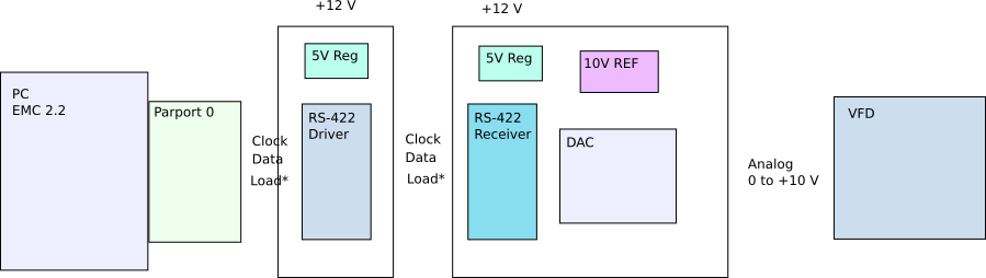
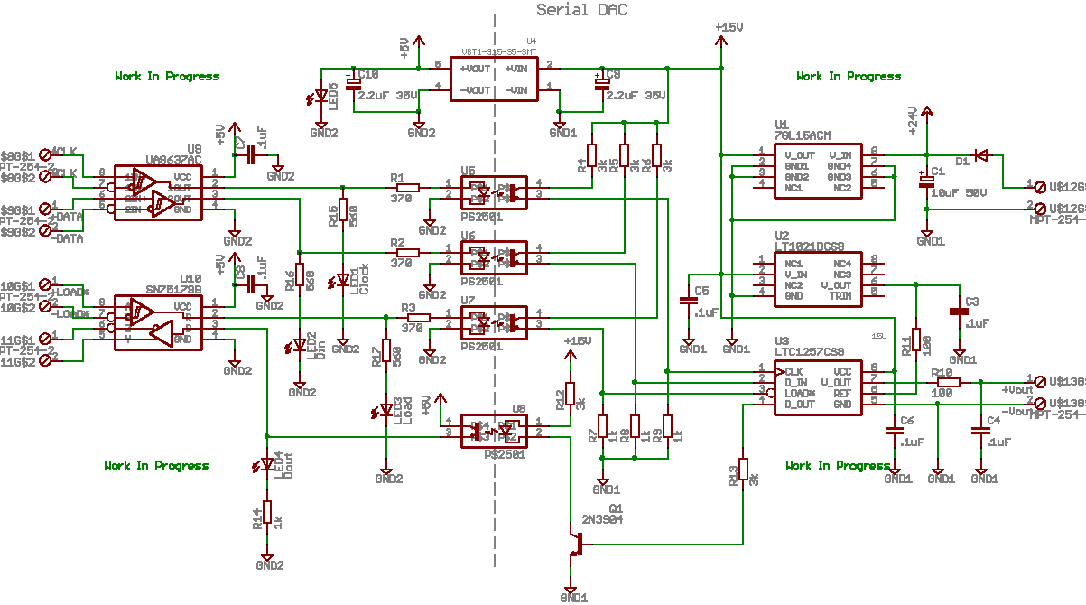
Serial DAC ProjectI have VFD's driving the spindle motors for my Bridgeport and a couple of lathes. Other than some torque issues at low speed, they work pretty well. In addition to driving spindles, I found small VFD's on eBay cheap enough to use as three-phase converters for coolant pumps. They are proving to be quite handy. This page will contain the information I gather for developing an adapter between EMC and VFD's, or more generally, a DC analog adapter My VFD's are set up to be controlled by a 0 to 10 Volt analog signal for speed and sinking Forward or Reverse to a Control Common terminal for rotation direction. An overview of my plan so far is shown below.
The DAC is a Linear Technologies LTC1257 12 bit unipolar converter. It has just the features I need, which helps to make it easier to implement than more complex DAC's. The software interface with EMC is an HAL component. It has an input pin for the value to convert to a binary bit stream output pin, plus output pins for Clock and Load*. Latest Files
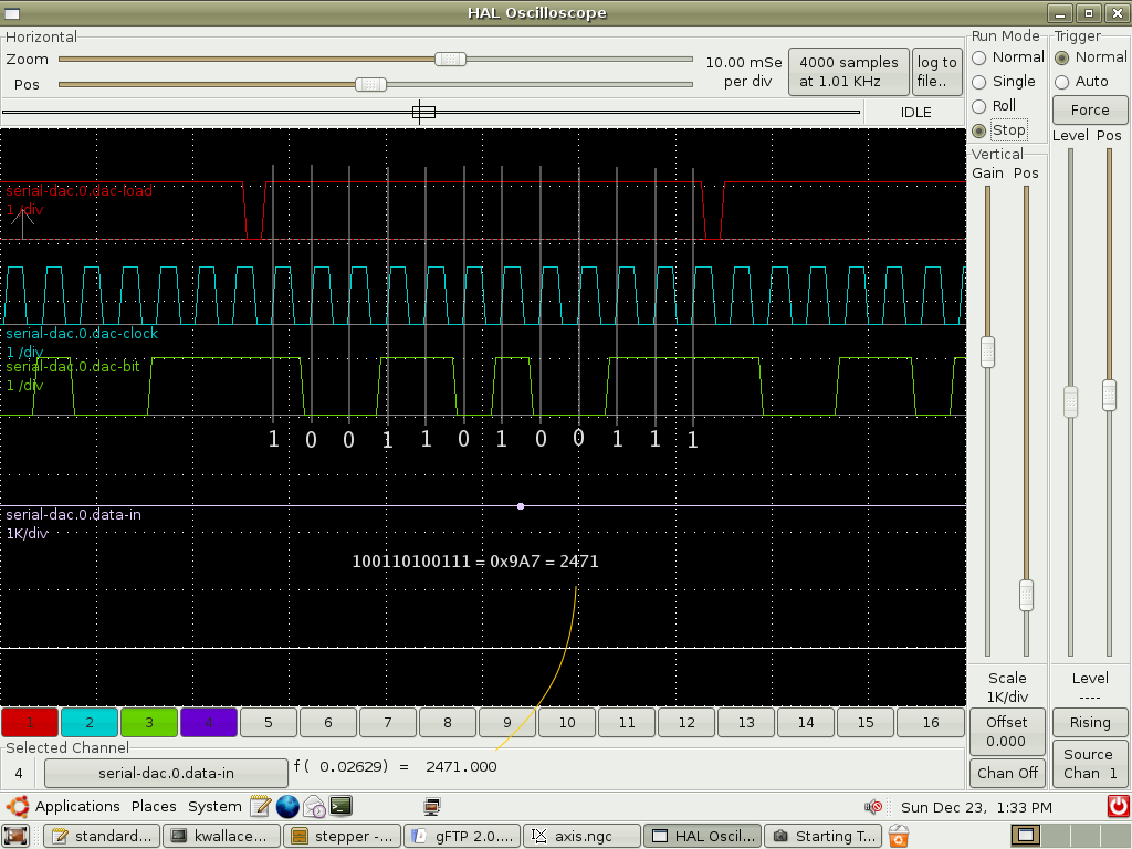
( Rev. 1 of this page) The software is now working well enough to test the hardware, which is yet to be built. The Halscope screen shot below is from a previous revision of the software, but should represent the current software, except I currently run the data out portion of the serial_dac component in the much faster base thread.
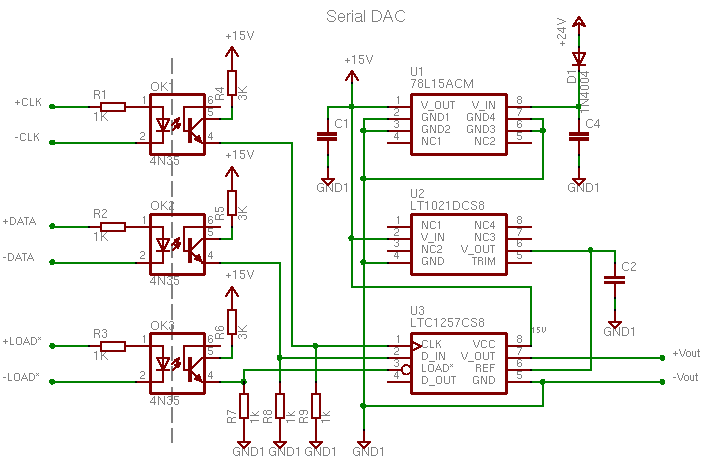
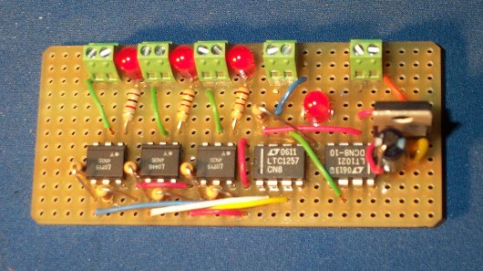
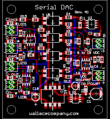
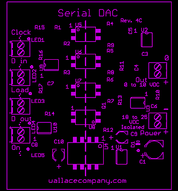
(2007/02/01) The board below is just missing the power input diode from the schematic. It's just there to protect the board, if the power is connected backwards. I tested the board with my VFD's and KBIC controller and it works just fine. The input and output remain isolated if you use an isolated power supply (18 to 30 Volt DC at 150 mA or higher wall wart), so it works with the KBIC, but you can't touch any part of the board because it is floating at about 70 Volts AC. The VFD's don't seem to float at high voltage, but it's a good idea to keep things isolated anyway. One VFD could not accept just an analog voltage. It needed a potentiometer across three terminals to work. The DAC can be swapped with a digital potentiometer in this circuit to make it work. I am also looking into a DAC solution. I am also thinking about what can be done to help protect the analog output. Maybe by using a 10 Volt Zener diode to clamp the output to 10 Volts.
|