|
Conversion of Hardinge HNC to EMC
Link to HNC EMC2 files New pictures are added to the top of the page. |
|
|
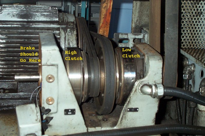
This picture shows the high/low spindle speed clutch assembly. The motor pulley is one piece. The clutch pulleys "float" on the output shaft. The output shaft turns at high or low speed depending on which clutch is engaged. If neither clutch is engaged, the output shaft is not driven (stops). If both clutches are engaged the different pulley ratios cause the system to bind, causing the output shaft to brake or break. (2008/03/08) |
|
|
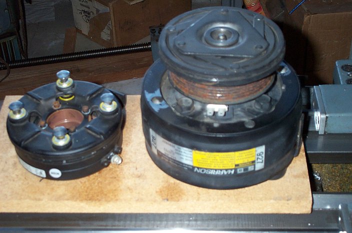
The high/low speed clutches are similar in design to the clutch on an automobile air conditioner pump, shown on the right. A Warner electric brake is shown on the left. This is very similar to the Warner electric release brake that should be mounted to the high/low speed assembly. A replacement Warner brake costs several hundred dollars, so I am considering alternatives, such as a shop-made pneumatic release brake. Because the air conditioner pump clutch is similar to the high/low clutches, I am thinking they could be used for high/low speed assemblies for smaller lathes and mills. (2008/03/08) |
|
|
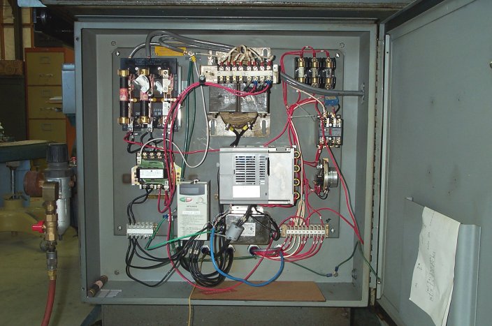
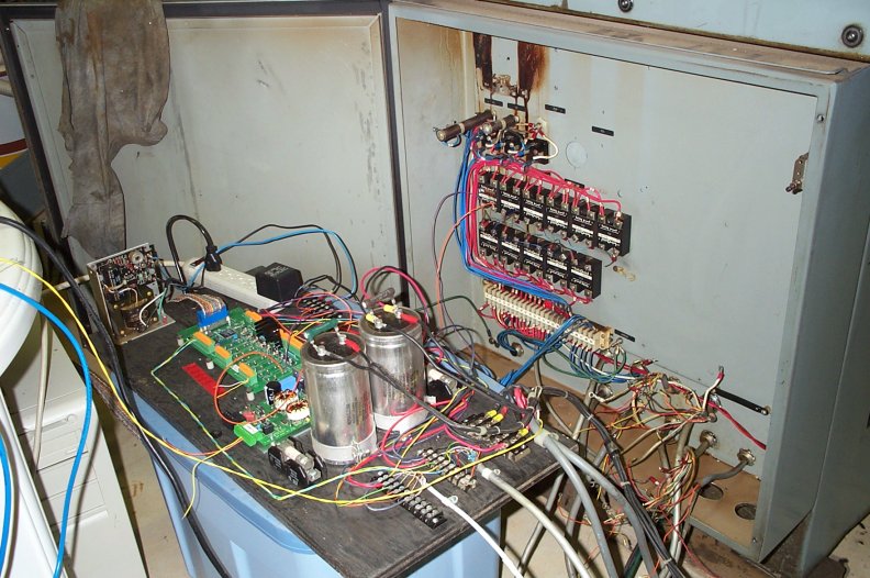
The right side or power cabinet with 240 Volt main cut-off and fuses on the upper left, secondary power relay just below, servo motor power transformer upper middle, spindle VFD below the transformer and the VFD line filter just below the VFD. To the left of the filter is the coolant VFD. 120 Volt main, oiler and oiler timer fuses are at the top right. Below the fuses are the oiler relay and oiler timer. |
|
|
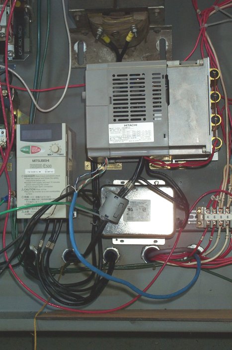
Closer view of the VFD's. The gray cylinder is a ferrite bead on the spindle motor lines. The coolant VFD line filter and ferrite bead have yet to be installed. |
|
|
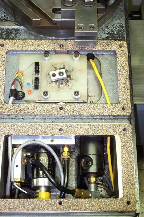
This is a top view of the rear half of the carriage. The turret encoder is in the middle. The turret pneumatic motor is in the lower right and the pneumatic solenoid and control in the lower left. |
|
|
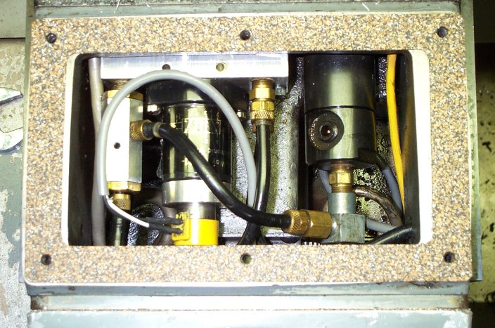
Closer view of the turret rotator section. |
|
|
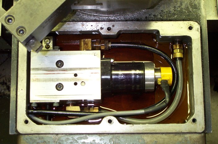
Top view of front of carriage showing the stop solenoid and valve body. |
|
|
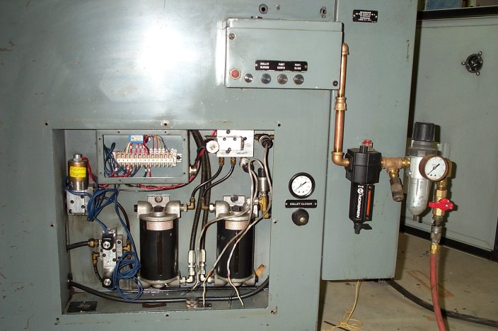
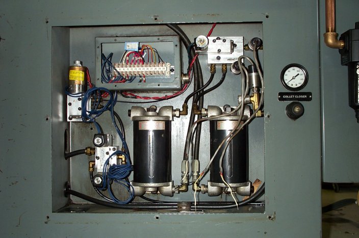
This area controls the cut-off slide, part chute, collet closer and pneumatic pressure and guard door alarms. |
|
|
|
|
|
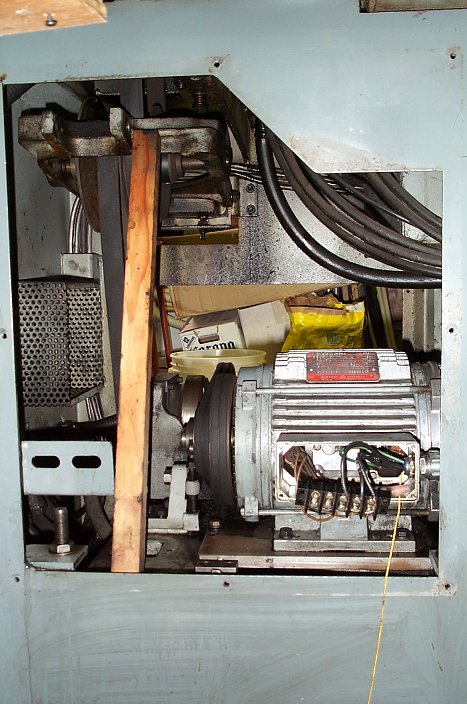
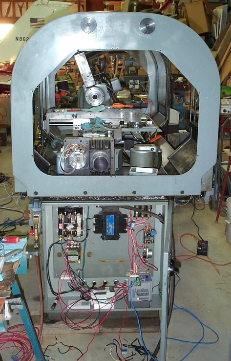
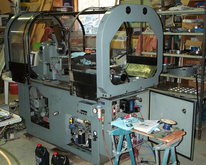
Work in progress in the spindle motor area. I need to replace the variable speed pulley assembly with a single belt and tensioner, but it's working okay as is, so it may be this way for a while. The two speed clutches are hidden behind the motor. I also need to fit an e-stop brake on the clutch assembly. |
|
|
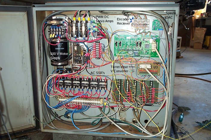
Left or Logic cabinet |
|
|
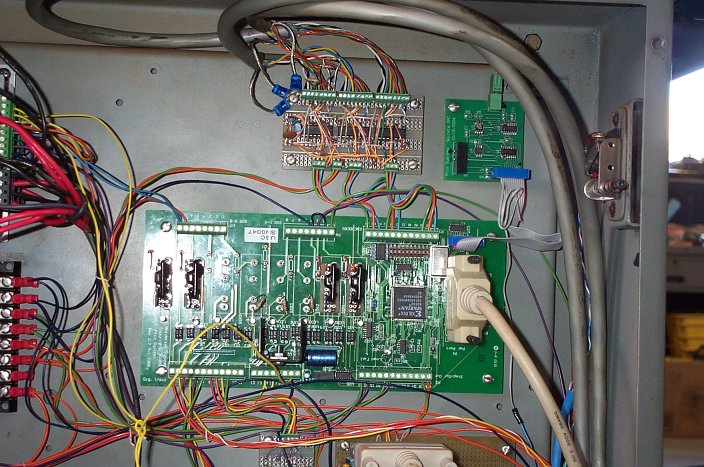
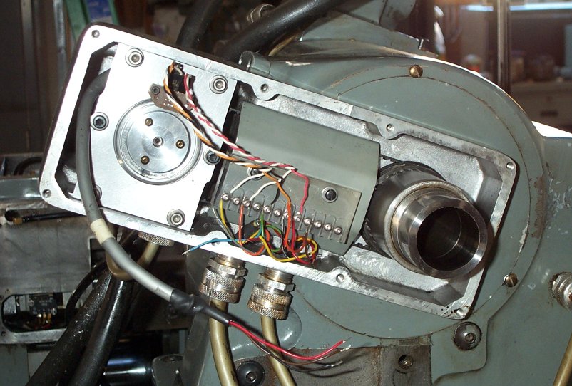
Closer view of the spindle differential receiver and Universal PWM Controller |
|
|
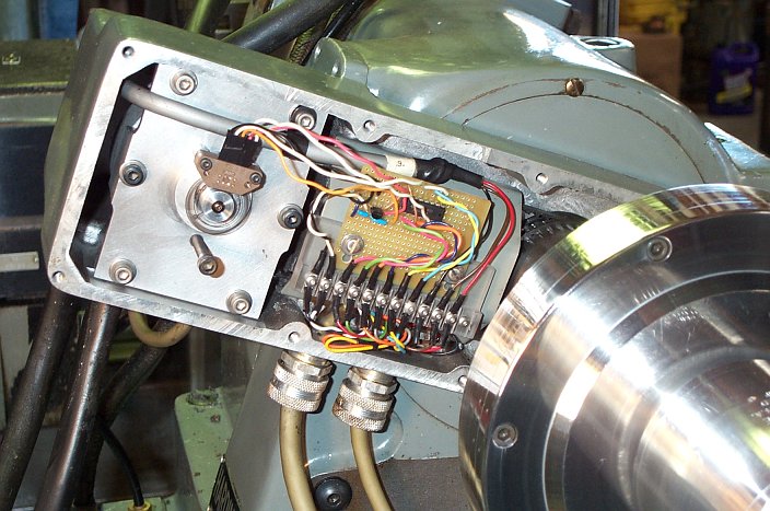
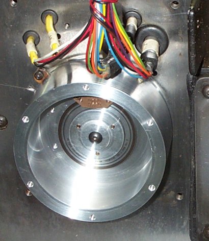
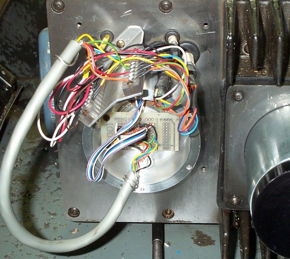
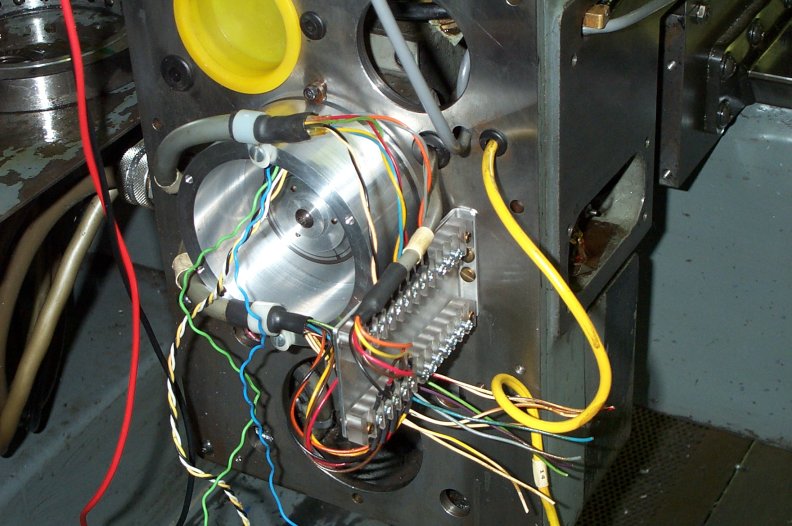
Spindle encoder and differential transmitter |
|
|
U. S. Digital 2500 cpr (10000 ppr) 2" disk with EM1 encoder module. |
|
|
I replaced the three phase relays with two VFD's. One for the spindle motor and a second for the coolant pump. |
|
|
The variable speed pulley assembly in the lower left will be removed. |
|
|
Shop made terminal strips and encoder differential driver. |
|