(Added driver board and schematic to bottom of page - 2007/08/10)
(Added another (hopefully improved) driver board and schematic to bottom of page - 2008/01/14)
The goal is to upgrade the current system to support a 360 degree view of the horizon. Currently the components are a PC running Linux, a digital camera, and cables. The upgrade components are a antenna rotor, weather resistant camera housing, and cables.
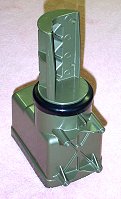
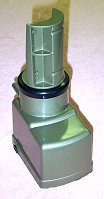
The rotor is from a GE TV antenna rotor and controller kit (model: TV94784) which I found on eBay for less than $50.00 . I won't be using the controller because it can not be easilly controlled by the PC.
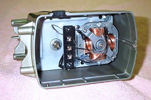
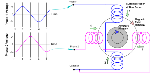
The motor that drives the rotor is an induction motor. My understanding of induction motors, so far, is that the armature is of a magnetic material but is not a permanent magnet nor is magnetized with electro-magnetic windings. When the motor is first energized, one of the stator windings creates a magnetic field around the armature. In response, the armature takes on a sympathetic magnetic field (which actually tends to prevent the armature from turning). Then the stator winding located 90 degrees to the first stator winding is energized while the first stator winding is de-energized. The second stator rapidly builds a new magnetic field 90 degrees away, but the armature can not change its field nearly as rapidly, so it tries to physically rotate to align its field with the new stator field. The stator windings are successively energized/de-energized to create a rotating field, which the stator will constantly try to catch up with.
I used an oscilloscope to determine that there are two 24 volt, 60 Hz AC signals coming from the controller to the rotor. A graph of the signals and a motor schematic for clockwise rotation is shown below. Changing the Phase 2 signal from 90 degrees (electrically 180 degrees) ahead to 90 degrees behind reverses the rotation to counter-clockwise.
Below are modifications to the signals and motor connections to allow a PC to create pulsed 24 volt DC to replace the original controller's 24 volt AC. This attempt requires circuitry to switch every other pulse to reverse the current through the signal's corresponding stator winding.
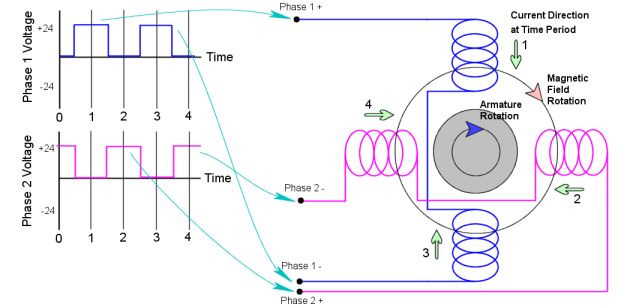
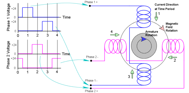
Below I added two more signals to allow the use of a "Full Bridge" driver detailed later.
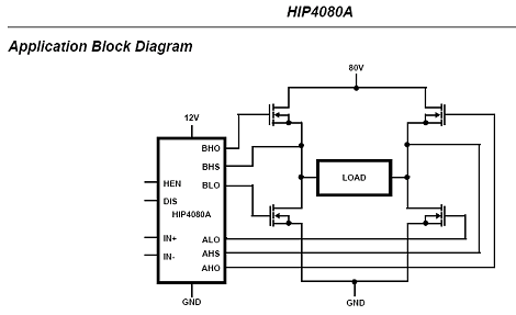
Below is a diagram of a Full Bridge Driver circuit. Two will be needed. One for each phase winding. I will use four of the data outputs on the PC's printer port to drive the driver's inputs.
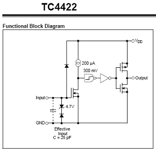
Below is a diagram of the Half Bridge Driver chip that I will be using. Four will be needed.
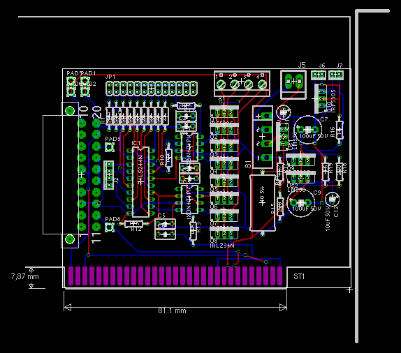
Below is a drawing of the planned rotor driver board. It has a PC-XT form factor to make it easy to mount and connect to 5 and 12 volt power to a back-plane. I tried etching my own board, but I could not get the front and back sides to register well enough. That was about a year ago, and I haven't touched it since.
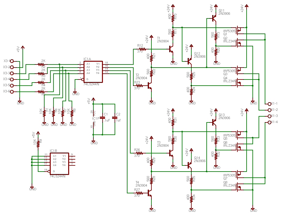
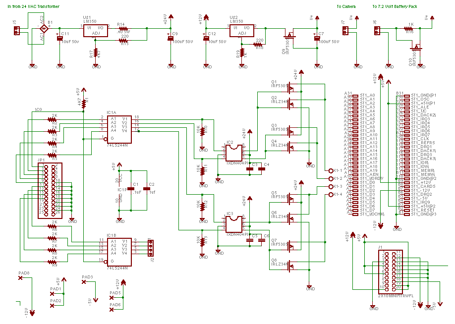
Below is the schematic of the rotor driver board. I am not an electronics engineer by any means. Much of this is copied from similar designs or I just guessed. The bread board version works well, so the design can't be too bad.
JP1 is a double row .1" pin header which connects to the computer printer port. X1-1 through X1-4 are the connections going to the rotor's motor windings. If I recall correctly, the voltage regulator circuit at the top center is a trickle charger for the camera backup battery.
(2008/01/14) A recent e-mail message I got, pointed out some flaws with my schematic (thank you, Jon D). One was, the gate to source voltage on the FET's was above the maximum called out in the datasheet. Generally, the maximum voltage is 20 Volts, I had 24 Volts. Another problem is that I had the P and N gates on the FET's tied together, which in a steady state, on or off, is not a problem. The problem comes about when the control signal is in transition. There is a region between the off and on voltage where both high and low FET's will be on, which causes a short. I went back to the literature that I referred to when making the schematic, and sure enough, this issue was brought up. This text indicated, for the particular application, the transition period was brief enough to not be a problem. For my schematic, the high voltage was a clear problem and the transitional short just seemed like sub-optimal design. With the new information in mind, I went back to the Internet to do more research on FET H-bridges. I found these links to be helpful:
http://www.cadvision.com/blanchas/hexfet/np-s.htm
http://ozitronics.com/docs/k166.pdf
http://www.irf.com/technical-info/appnotes/an-978.pdf
http://www.irf.com/technical-info/appnotes.htm
Above, I mentioned that I might try to use an HIP4080 as a driver, but during my recent research, I learned that this type of driver is used with a bridge with four N-channel FET's. The caveat here is, that an N-channel FET needs a positive gate-source voltage to turn on. The source pins on the upper FET's are at the positive supply voltage, 24 Volts, so I would need 34 Volts on the gates to turn them on. The HIP4080 has a boot-strap circuit that supplies the needed voltage, but the boot-strap only gets charged when the lower FET's turn off, typically with a PWM input. My first schematic has P-channel upper FET's, which turn on with a negative gate-source voltage, so no boot-strap is needed. I was going to say, I could not use the HIP4080 because I don't have a PWM input signal, but as I started this sentence, I realized that I will have a 60Hz input signal, which should be adequate. The following schematic is Eugene Blanchard's design adapted to my application. I may try another design based on the HIP4080 in the near future. I have not built or tested this circuit, so I don't even know if it works, or is good for anything other than taking up e-space.